Concrete Wall Strengthening
Last updated March 10, 2026
By Ian Story
Often, we need to strengthen an existing concrete wall to support new construction. This can occur, for example, when repairing an under-sized retaining wall in place.
There are two general approaches to this problem: the simpler and more conservative is to design the new concrete layer to resist all forces. In this case we pretend like the old concrete doesn’t exist, treating it as stay-in-place formwork rather than a structural element. But where space is tight or we need as much capacity as we can get, there are options to incorporate the existing concrete into the new system so that the whole assembly acts as one composite assembly.
The best option for doing this is to use ACI’s shear friction provisions, but there are some significant problems here. ACI requires shear friction rebar to be developed to its full yield strength, which requires a facing wall at least 8 inches thick (6 inch hooked bar development length, plus 2 inches of concrete cover), and an even thicker existing wall to fully develop an epoxy anchor connection. In practice, I have never seen a situation where this is viable for residential work – by the time you get to an 8 inch thick facing wall, it is much easier to just design that wall to take 100% of the loads).
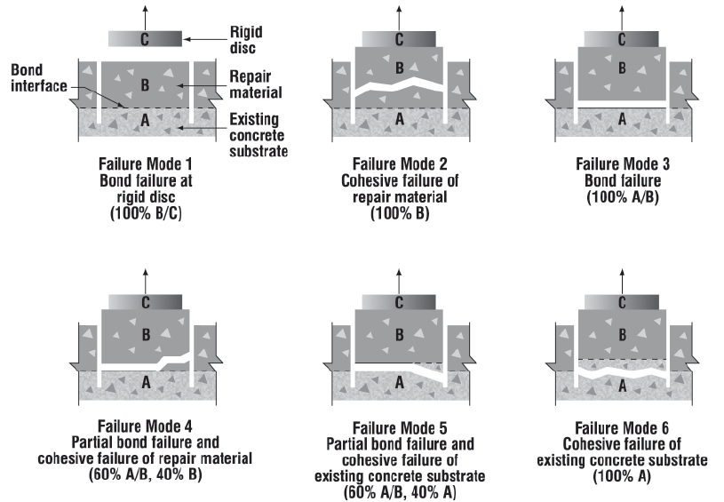
The other option is to rely on bond strength between the two layers, with supplemental dowel anchorage as a structural backup. The literature on this topic generally notes that properly roughened concrete can develop an interface shear strength of around 200 psi with no reinforcement across the joint. This is a different mechanism from friction – it is based on a cohesion bond between the concrete surfaces and is considered much stiffer than other available modes of interface shear resistance (friction or dowel strength). Accordingly, ACI allows only one of the two – cohesion or friction, but not both at the same time.
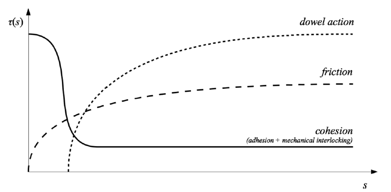
(source: Interface Shear Transfer on Composite Concrete Members, by Pedro M. D. Santos and Eduardo N. B. S. Júlio. ACI Structural Journal Technical Paper No. 111-S11)
The provisions for cohesion-based interface shear can be found in ACI 318-19 section 16.4: Horizontal shear transfer in composite concrete flexural members. Note that the term “horizontal shear” in this title is misleading. In the concrete research literature, the term “horizontal shear” is used to refer to inter-layer shear in beams or slabs, to differentiate it from “vertical shear” through the thickness of the member. This is a historical term, based on the fact that most concrete flexural members are cast in a horizontal position. To highlight this, this article from the PCI Journal discusses the process of Horizontal Shear Design across the wythes of a precast concrete wall panel:
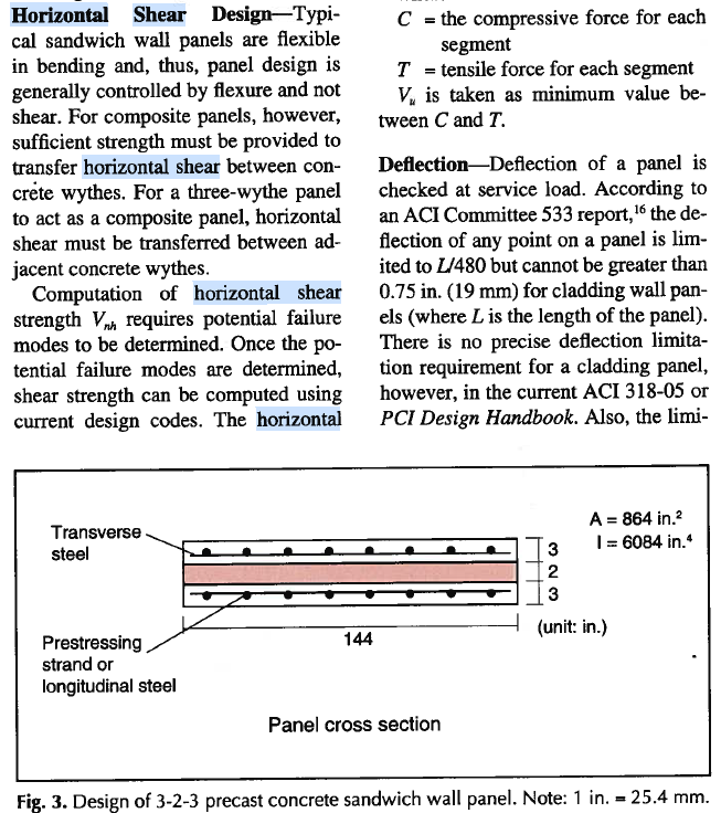
(source: Design and Analysis of Precast, Prestressed Concrete, Three-Wythe Sandwich Wall Panels by Byoung-Jun Lee and Stephen Pessiki, PCI Journal July-August 2007 pp. 70-83)
For layered concrete without explicitly designed and developed shear reinforcement across the joint, ACI allows a maximum nominal shear equal to 80bd pounds, where b is the contact width of the surface and d is the depth to neutral axis of the flexure section. For a distributed surface like a slab, this translates to a limit of 80d lb/in or 960d lb/ft, which is a substantial amount of shear that can be handled based purely on the bond between layers. Note that this still needs to be factored down by the strength reduction factor to get design values, and converted to ASD for service level load design. Also note that proper surface preparation (roughening to 1/4 inch, removing laitance) is required to make use of interface shear.
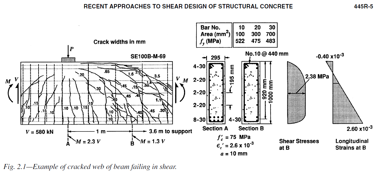
The “80” term represents a nominal interface shear stress of 80 psi selected as a conservative value by ACI based on empirical testing. This is based on the following simplified constant shear flow equation used for the web zone of cracked concrete members:
![\[v = \frac{V}{bd}\]](https://modearchitecture.com/wp-content/ql-cache/quicklatex.com-b68a3233af7be825a4b8201893d23b69_l3.png "Rendered by QuickLaTeX.com")
Note that this is different from the classical derivation for a homogeneous rectangular beam under elastic bending ( ), which would yield a parabolic shear flow with a peak value of:
![\[v_{peak,homogeneous} = \frac{3}{2}\frac{V}{bd}\]](https://modearchitecture.com/wp-content/ql-cache/quicklatex.com-3cfe34c2d50dda47663a933444167a9a_l3.png "Rendered by QuickLaTeX.com")
I have been unable to locate a fully satisfying mechanical explanation for this difference. The key logic seems to hinge on the difference between an elastic section versus the truss model used to describe reinforced concrete beams.
Accordingly, the ACI equation does not consider the exact interface location when determining the allowable sectional shear, which simplifies the design.
In addition to the nominal strength provisions, ACI also provides guidance when using interface shear for repairs in ACI 562-19 Code Requirements for Assessment, Repair, and Rehabilitation of Existing Concrete Structures. Here they discuss bond stress in interface shear stress (psi), specifying peak shear stress  , where
  . Using 80 psi as a baseline gives a design
  of 60 psi.
ACI 562 includes two threshold values relevant to this discussion:
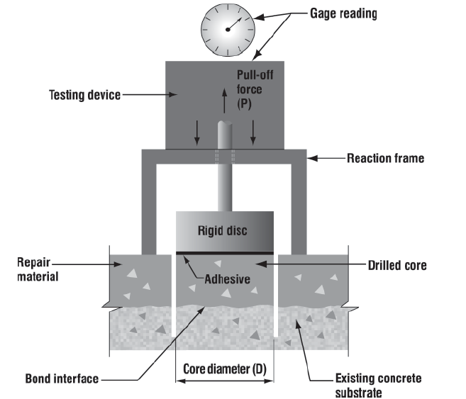
- For an ultimate interface shear below 60 psi, the code does not require interface reinforcement, but it does require testing (using the direct tension pull-off test) to verify this capacity.
- For an ultimate interface shear below 30 psi, the bond is assumed sufficient and the designer is left to specify their choice of bond integrity testing.
For residential design, we generally want to avoid extra testing where feasible. Therefore we try to keep the required interface shear stress below 30 psi for our composite concrete sections.
Additionally, we typically specify mechanical anchorage across the interface joint. While this is not required by code, it provides a bit of redundancy and helps with placing the rebar mat. Using a 3 inch facing wall as an example, we might specify 3/8″ diameter hex bolts epoxied into the existing wall to act as headed studs. For anchors with a min. 3″ epoxy embedment depth and sufficient spacing to avoid edge effects or overlapping breakout codes, this gives a single-anchor shear capacity of 1,500 pounds per anchor (service level forces, controlled by pryout for the shallow 1 3/4″ embedment of the hooked anchor). Matching the 30 psi minimal interface shear capacity would require a tributary area of 50 square inches per anchor, or anchors at 7 inches on center. This is too dense, and the anchors interfere with each other at that spacing.
Using an anchor spacing of 12 inches on center gives an equivalent 10.4 psi interface shear.
Using an anchor spacing of 18 inches on center gives an equivalent 4.6 psi interface shear.