Detail Drafting Views
Last updated July 7, 2022
By Emma Howland
Creating New Detail Families:
- File>New>Family>English-Imperial>Detail Item (use “Detail Item- Line Based” for detail items that can be stretched)
- From CAD file: Import CAD
Common Details:
Foundation Details
- Typical Exterior Foundation
- Typical Interior Foundation detail (if different)
- Typical Hold-down details
Floor Framing
- Typical Floor Framing @ exterior wall (detail separately for joists parallel & joists perpendicular)
- Typical Floor Framing @ interior
- Interior Shear wall connection w/ no wall above (detail separately…)
- Shear wall above with no wall below (detail separately…)
- Typical interior Shear wall (detail separately…)
- Strap details
- Beam fastener schedules
- Changes in floor level
Roof Framing
- Typical Eave Framing
- Typical Rake Eave Framing
- Typical Gable Truss elevation
- Interior shearwall parallel with trusses
- Interior shearwall perpendicular to trusses
- strap details
Deck Details
- Ledger connection
- Weather deck drain
- Weather deck edge
Guardrail Details
- Interior guardrail attachment
- Exterior guardrail attachment
Detail Notes
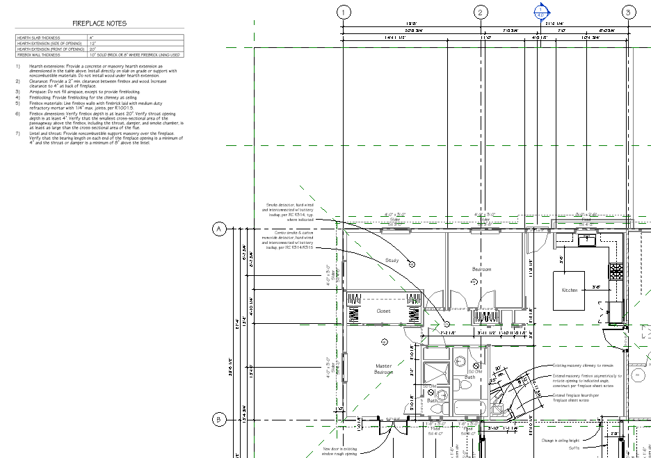
- Detailing may not require a separate detail on a page. There may be instances where including a separate note section on a floor plan sheet will suffice. For example, detailing a remodeled fireplace per IRC 2015 (see below)
- In this project the firebox and hearth are being extended and require some general notes that reference the code requirements to be met during construction.
- After reading through the code chapter on fireplaces, we composed a list of the code sections that are relevant to the contractors.
- This project also had a table that was simplified and transcribed onto the sheet notes with only the relevant measurements.
- Next, we simplify the notes (and translate them out of “legal-ese” language)
- Remove explicit references to ASTM standards, etc. , but be sure to check your understanding of those codes and retain the relevant information in the note.

General Drafting Standards for Details:
- Check alignment of reference planes with all other details by copying and pasting in place the reference planes of a known updated detail
- HT (Halftone) existing materials
- Align cuts to material edges. If the majority of materials being cut are existing, the cut can be made HT
- Use “Framing Member – Side” or “cur lumber” component to show framing members only, use a white fill to show trim members
- Check drawing order of all elements (particularly nails- they should be shown in front)
- For finish details only: outline the cut elements with a Wide Line
- Check to make sure all flashing is shown as a Wide Line (this is one of the most important pieces of the detail and should be easy to see)
- Notes should typically reference “per plans” or “per framing details”
- Typically, floor sheathing sits below reference plane and sill plate sits above reference plane. Top plate sits below reference plane
- For detail notes
- make sure all arrows are touching the exact member/ condition it is referring to
- Make sure that the note alignment is correct depending on which side of the drawing the note is on (Left align for notes on the right side, Right align for notes on the left)
- The arc of each arrow leader should decrease evenly among notes depending on how much room there is for notes- for example, they may all have a rainbow arc if there is plenty of room, otherwise the notes on top should have rainbow arcs, decreasing to a straight leader in the middle, then decreasing to a flipped arc at the bottom of the detail
- (hint- Do not move the middle anchor point on the arc)
- If there is a series of notes that are related (Ex. Typical Rake Eave, Unique Rake Eave @ Deck overhang) and there is a lot of overlap between notes, you can remove the repeat text from the unique detail and add a note without an arrow reading “See Typical ___ Detail for additional notes”
- Add “Last Updated” date
Laying up on a Sheet
- Vertical Space from bottom of sheet: 7/8″
- Horizontal space from Title block: 1/4″
- Vertical space between details: 1″
- Horizontal space between details: 1/4″
Typical Wall Section
- Make sure the reference planes correlate with the number of stories- a 2 story house should be contained within (3) views.
- Starting from the bottom section, check the following conditions in the foundation, floor, and wall framing plans to show in the detail:
- Footing Dimensions
- Stem Wall Dimensions
- Floor framing member size
- Hanger type/ Rim joist?
- Size of studs (2x4s/ 2x6s?)
- Roof framing members (trusses/ rafters)
- Roof pitch
- Eave dimensions
Recent Posts
Categories
- Accessibility (2)
- Annotation Templates (1)
- Building Code (6)
- Calculation Templates (2)
- Civil Engineering (3)
- Derivations (8)
- Drafting Standards (18)
- Energy Code (1)
- Geotechnical Engineering (2)
- IT & Software Setup (5)
- Land Use Code (1)
- Product Knowledge (9)
- Production Tutorial (7)
- Research Notes (9)
- Research Tips (1)
- Revit Families (2)
- Revit Tips (5)
- Standard Operating Procedures (6)
- Stormwater (4)
- Structural Calculators (4)
- Structural Engineering (30)
- Structural General (11)
- Uncategorized (29)