Finite Element: Q8 Quadrilaterals
Last updated August 30, 2023
By Ian Story
The following are notes that may be helpful when implementing the stiffness matrix for a Q8 quadrilateral. These notes supplement the following YouTube lectures by Dr. Clayton Pettit:
Finite Element Method: Quadrilateral Elements
Finite Element Method: Isoparametric Elements
Shape Functions
Throughout this derivation, we will use the following shape functions:
![]()
![]()
![]()
![]()
![]()
![]()
![]()
![]()
To simplify display in matrices, the function arguments ![]() are omitted in the following derivation. Just remember that everywhere
are omitted in the following derivation. Just remember that everywhere ![]() appears, it actually means
appears, it actually means ![]() , a function that must be evaluated at every point in the natural coordinate system.
, a function that must be evaluated at every point in the natural coordinate system.
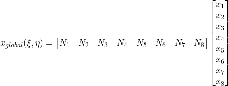
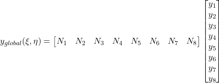
Coordinate Mapping


Jacobian Matrix
 =\renewcommand*{\arraystretch}{2.5}\begin{bmatrix}\cfrac{\partial x}{\partial \xi} & \cfrac{\partial x}{\partial \eta} \\\cfrac{\partial y}{\partial \xi} & \cfrac{\partial y}{\partial \eta}\end{bmatrix}](https://modearchitecture.com/wp-content/ql-cache/quicklatex.com-422fff329b7371f7285905a075d14ad3_l3.png)
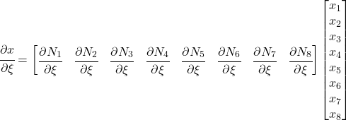
Where:

The partial derivative for y and partial derivatives with respect to ![]() are identical to the above: just swap out the relevant symbols.
are identical to the above: just swap out the relevant symbols.
Making use of the ![]() matrix, presented below, the Jacobian matrix can be expressed as follows:
matrix, presented below, the Jacobian matrix can be expressed as follows:
 = [\partial N](\xi, \eta)\begin{bmatrix}x_1 & y_1 \\x_2 & y_2 \\x_3 & y_3 \\x_4 & y_4 \\x_5 & y_5 \\x_6 & y_6 \\x_7 & y_7 \\x_8 & y_8 \end{bmatrix}](https://modearchitecture.com/wp-content/ql-cache/quicklatex.com-26cb055b4ec1c00d7b482d899568d0d3_l3.png)
 N Matrix
To simplify further calculations, we can define a ![]() N matrix as follows:
N matrix as follows:
 =\renewcommand*{\arraystretch}{2.5}\begin{bmatrix}\cfrac{\partial N_1}{\partial \xi} & \cfrac{\partial N_2}{\partial \xi} & \cfrac{\partial N_3}{\partial \xi} & \cfrac{\partial N_4}{\partial \xi} & \cfrac{\partial N_5}{\partial \xi} & \cfrac{\partial N_6}{\partial \xi} & \cfrac{\partial N_7}{\partial \xi} & \cfrac{\partial N_8}{\partial \xi} \\\cfrac{\partial N_1}{\partial \eta} & \cfrac{\partial N_2}{\partial \eta} & \cfrac{\partial N_3}{\partial \eta} & \cfrac{\partial N_4}{\partial \eta} & \cfrac{\partial N_5}{\partial \eta} & \cfrac{\partial N_6}{\partial \eta} & \cfrac{\partial N_7}{\partial \eta} & \cfrac{\partial N_8}{\partial \eta}\end{bmatrix}](https://modearchitecture.com/wp-content/ql-cache/quicklatex.com-800e43fb1ab73787660262d17f36365f_l3.png)
Where:
![]()
![]()
![]()
![]()
![]()
![]()
![]()
![]()
![]()
![]()
![]()
![]()
![]()
![]()
![]()
![]()
B Matrix Derivation
 =\begin{bmatrix}\epsilon_{xx} \\\epsilon_{yy} \\\gamma_{xy}\end{bmatrix} =\begin{bmatrix}\epsilon_{xx} \\\epsilon_{yy} \\\epsilon_{xy} + \epsilon_{yx} \\\end{bmatrix} =\renewcommand*{\arraystretch}{2.5}\begin{bmatrix}\cfrac{du}{dx} \\\cfrac{dv}{dy} \\\cfrac{du}{dy} + \cfrac{dv}{dx} \\\end{bmatrix} =\renewcommand*{\arraystretch}{1.0}\begin{bmatrix}1 & 0 & 0 & 0 \\0 & 0 & 0 & 1 \\0 & 1 & 1 & 0\end{bmatrix}\renewcommand*{\arraystretch}{2.5}\begin{bmatrix}\cfrac{du}{dx} \\\cfrac{du}{dy} \\\cfrac{dv}{dx} \\\cfrac{dv}{dy}\end{bmatrix}](https://modearchitecture.com/wp-content/ql-cache/quicklatex.com-ad4a3c4df44be0c2325e571249546e49_l3.png)
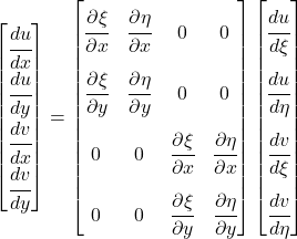
Where (by multivariable chain rule):
![]()
![]()
![]()
![]()
Or, in matrix form:

Conveniently, the first matrix can be simplified based on existing information, because:
^{-1})^T](https://modearchitecture.com/wp-content/ql-cache/quicklatex.com-24a55d466a4b3a7d5f0f3490dd45396e_l3.png)
Because ![]() and
and ![]() are just the nodal displacements at
are just the nodal displacements at ![]() and
and ![]() , the same coordinate mapping applies here:
, the same coordinate mapping applies here:

Therefore:

Replacing the nodal displacements with a vector, ![Rendered by QuickLaTeX.com [u] =\begin{bmatrix}u_1 \\v_1 \\\vdots \\u_8 \\v_8 \\\end{bmatrix}](https://modearchitecture.com/wp-content/ql-cache/quicklatex.com-803c5bfaefbd29a50b40c33a58797627_l3.png) ,
,
![Rendered by QuickLaTeX.com \renewcommand*{\arraystretch}{2.5}\begin{bmatrix}\cfrac{du}{d\xi} \\\cfrac{du}{d\eta} \\\cfrac{dv}{d\xi} \\\cfrac{dv}{d\eta}\end{bmatrix} = \renewcommand*{\arraystretch}{2.5}\setcounter{MaxMatrixCols}{20}\begin{bmatrix}\cfrac{\partial N_1}{\partial \xi} & 0 & \cfrac{\partial N_2}{\partial \xi} & 0 & \cfrac{\partial N_3}{\partial \xi} & 0 & \cfrac{\partial N_4}{\partial \xi} & 0 & \cfrac{\partial N_5}{\partial \xi} & 0 & \cfrac{\partial N_6}{\partial \xi} & 0 & \cfrac{\partial N_7}{\partial \xi} & 0 & \cfrac{\partial N_8}{\partial \xi} & 0 \\\cfrac{\partial N_1}{\partial \eta} & 0 & \cfrac{\partial N_2}{\partial \eta} & 0 & \cfrac{\partial N_3}{\partial \eta} & 0 & \cfrac{\partial N_4}{\partial \eta} & 0 & \cfrac{\partial N_5}{\partial \eta} & 0 & \cfrac{\partial N_6}{\partial \eta} & 0 & \cfrac{\partial N_7}{\partial \eta} & 0 & \cfrac{\partial N_8}{\partial \eta} & 0 \\0 & \cfrac{\partial N_1}{\partial \xi} & 0 & \cfrac{\partial N_2}{\partial \xi} & 0 & \cfrac{\partial N_3}{\partial \xi} & 0 & \cfrac{\partial N_4}{\partial \xi} & 0 & \cfrac{\partial N_5}{\partial \xi} & 0 & \cfrac{\partial N_6}{\partial \xi} & 0 & \cfrac{\partial N_7}{\partial \xi} & 0 & \cfrac{\partial N_8}{\partial \xi} \\0 & \cfrac{\partial N_1}{\partial \eta} & 0 & \cfrac{\partial N_2}{\partial \eta} & 0 & \cfrac{\partial N_3}{\partial \eta} & 0 & \cfrac{\partial N_4}{\partial \eta} & 0 & \cfrac{\partial N_5}{\partial \eta} & 0 & \cfrac{\partial N_6}{\partial \eta} & 0 & \cfrac{\partial N_7}{\partial \eta} & 0 & \cfrac{\partial N_8}{\partial \eta}\end{bmatrix}[u]](https://modearchitecture.com/wp-content/ql-cache/quicklatex.com-90aa9a19c9fdecfde2c7beace4d2768f_l3.png)
This 4×16 matrix is just the ![]() matrix with zero columns inserted between each column, repeated and offset by one column. Therefore, let us define:
matrix with zero columns inserted between each column, repeated and offset by one column. Therefore, let us define:
![Rendered by QuickLaTeX.com [\partial N2] \equiv\renewcommand*{\arraystretch}{2.5}\setcounter{MaxMatrixCols}{20}\begin{bmatrix}\cfrac{\partial N_1}{\partial \xi} & 0 & \cfrac{\partial N_2}{\partial \xi} & 0 & \cfrac{\partial N_3}{\partial \xi} & 0 & \cfrac{\partial N_4}{\partial \xi} & 0 & \cfrac{\partial N_5}{\partial \xi} & 0 & \cfrac{\partial N_6}{\partial \xi} & 0 & \cfrac{\partial N_7}{\partial \xi} & 0 & \cfrac{\partial N_8}{\partial \xi} & 0 \\\cfrac{\partial N_1}{\partial \eta} & 0 & \cfrac{\partial N_2}{\partial \eta} & 0 & \cfrac{\partial N_3}{\partial \eta} & 0 & \cfrac{\partial N_4}{\partial \eta} & 0 & \cfrac{\partial N_5}{\partial \eta} & 0 & \cfrac{\partial N_6}{\partial \eta} & 0 & \cfrac{\partial N_7}{\partial \eta} & 0 & \cfrac{\partial N_8}{\partial \eta} & 0 \\0 & \cfrac{\partial N_1}{\partial \xi} & 0 & \cfrac{\partial N_2}{\partial \xi} & 0 & \cfrac{\partial N_3}{\partial \xi} & 0 & \cfrac{\partial N_4}{\partial \xi} & 0 & \cfrac{\partial N_5}{\partial \xi} & 0 & \cfrac{\partial N_6}{\partial \xi} & 0 & \cfrac{\partial N_7}{\partial \xi} & 0 & \cfrac{\partial N_8}{\partial \xi} \\0 & \cfrac{\partial N_1}{\partial \eta} & 0 & \cfrac{\partial N_2}{\partial \eta} & 0 & \cfrac{\partial N_3}{\partial \eta} & 0 & \cfrac{\partial N_4}{\partial \eta} & 0 & \cfrac{\partial N_5}{\partial \eta} & 0 & \cfrac{\partial N_6}{\partial \eta} & 0 & \cfrac{\partial N_7}{\partial \eta} & 0 & \cfrac{\partial N_8}{\partial \eta}\end{bmatrix}](https://modearchitecture.com/wp-content/ql-cache/quicklatex.com-2990f94f62fbd59110d5327d39a2145f_l3.png)
Putting all the pieces together gives
 =\begin{bmatrix}1 & 0 & 0 & 0 \\0 & 0 & 0 & 1 \\0 & 1 & 1 & 0\end{bmatrix}\begin{bmatrix}([J](\xi, \eta)^{-1})^T & \begin{bmatrix}0 & 0 \\0 & 0\end{bmatrix} \\\begin{bmatrix}0 & 0 \\0 & 0\end{bmatrix} & ([J](\xi, \eta)^{-1})^T\end{bmatrix}[\partial N2]](https://modearchitecture.com/wp-content/ql-cache/quicklatex.com-a21a045b3562bb66b66eefb8721cf714_l3.png)
By the definition of the kinematic matrix (![]() )
)
![]()
Which implies
 =\begin{bmatrix}1 & 0 & 0 & 0 \\0 & 0 & 0 & 1 \\0 & 1 & 1 & 0\end{bmatrix}\begin{bmatrix}([J](\xi, \eta)^{-1})^T & \begin{bmatrix}0 & 0 \\0 & 0\end{bmatrix} \\\begin{bmatrix}0 & 0 \\0 & 0\end{bmatrix} & ([J](\xi, \eta)^{-1})^T\end{bmatrix}[\partial N2]](https://modearchitecture.com/wp-content/ql-cache/quicklatex.com-660b4ff1d1eefe68db833712c76f0876_l3.png)
C Matrix
Under plane stress,
 =\begin{bmatrix}\sigma_{xx} \\\sigma_{yy} \\\tau_{xy}\end{bmatrix} =\cfrac{E}{1-\nu^2}\begin{bmatrix}1 & \nu & 0 \\\nu & 1 & 0 \\0 & 0 & 1-\nu\end{bmatrix}\begin{bmatrix}\epsilon_{xx} \\\epsilon_{yy} \\\epsilon_{xy}\end{bmatrix}](https://modearchitecture.com/wp-content/ql-cache/quicklatex.com-6b6c7fbbba6603b9eeb41b57fdee62ca_l3.png)
By the definition of the constitutive matrix (![]() ):
):
![]()
Therefore,![Rendered by QuickLaTeX.com [C] = \cfrac{E}{1-\nu^2}\begin{bmatrix}1 & \nu & 0 \\\nu & 1 & 0 \\0 & 0 & 1-\nu\end{bmatrix}](https://modearchitecture.com/wp-content/ql-cache/quicklatex.com-f2fa24f87692bed5b9b2d610b6b10f9a_l3.png)
Element Stiffness Matrix
![]()
This integral can be simplified by using Gauss Integration (recommended n=3 for balance between performance and accuracy – this requires sampling the element at 9 points)
Tutorial: Dr. Clayton Pettit on Gaussian Integration
Post Processing
Once nodal deflections ![]() are known, the strains and stresses can be determined at any point on the element:
are known, the strains and stresses can be determined at any point on the element:
 =\begin{bmatrix}\epsilon_{xx} \\\epsilon_{yy} \\\gamma_{xy}\end{bmatrix} = [B](\xi,\eta)[u]](https://modearchitecture.com/wp-content/ql-cache/quicklatex.com-9af3440f22bb91a747f7b04b6783a0d2_l3.png)
 = \begin{bmatrix}\sigma_{xx} \\\sigma_{yy} \\\tau_{xy}\end{bmatrix} =[C][\epsilon_{2D}](x,y)](https://modearchitecture.com/wp-content/ql-cache/quicklatex.com-7c90b3f440880b740306ad1a05412e8f_l3.png)
![Rendered by QuickLaTeX.com \begin{bmatrix}\sigma_{xx} \\\sigma_{yy} \\\tau_{xy}\end{bmatrix} = [C][B](\xi,\eta)[u]](https://modearchitecture.com/wp-content/ql-cache/quicklatex.com-1899b7842fd7e23a27e8c85dfadd1678_l3.png)
Note that it is not easy to convert from the local/global coordinate systems to the natural coordinate system. Because all of the shape functions depend on inputs of ![]() and
and ![]() , working backwards requires a trial and error process until the
, working backwards requires a trial and error process until the ![]() guesses match the desired x, y outputs.
guesses match the desired x, y outputs.
Therefore, it is more typical to calculate stresses in the natural coordinate system at regular intervals and place these at their corresponding places in the local coordinate system.
More Helpful Reference
Recent Posts
Categories
- Accessibility (2)
- Annotation Templates (1)
- Building Code (6)
- Calculation Templates (2)
- Civil Engineering (3)
- Derivations (8)
- Drafting Standards (18)
- Energy Code (1)
- Geotechnical Engineering (2)
- IT & Software Setup (5)
- Land Use Code (1)
- Product Knowledge (9)
- Production Tutorial (7)
- Research Notes (9)
- Research Tips (1)
- Revit Families (2)
- Revit Tips (5)
- Standard Operating Procedures (6)
- Stormwater (4)
- Structural Calculators (4)
- Structural Engineering (30)
- Structural General (11)
- Uncategorized (29)