LFRS Process
Last updated October 11, 2024
By Emma Howland
General Set-up
- Copy/resave lateral calculator spreadsheet, and Structural calcs intro from most recent completed project in structural folder.
- Look up ATC Seismic hazards by location (ASCE7-16, Risk category II, Site Class D-default). Print results to structural folder
- Create LFRS Structural Plan Views
- Create new structural plan view labeled “LFRS Diagram – Existing Roof” (for 1 story house) or “LFRS Diagram – Upper Floor” (for 1 story house) with Associated Level: T.O. Sheathing. If 2-story house, Create another view with Associated level: Upper floor T.O. Sheathing labeled “LFRS Diagram – Existing Roof”. Duplicate views and label “LFRS Diagram – Roof”, etc.
- Make sure to adjust view ranges and Phasing accordingly to see existing/ new construction
- Create new structural plan view labeled “LFRS Diagram – Existing Roof” (for 1 story house) or “LFRS Diagram – Upper Floor” (for 1 story house) with Associated Level: T.O. Sheathing. If 2-story house, Create another view with Associated level: Upper floor T.O. Sheathing labeled “LFRS Diagram – Existing Roof”. Duplicate views and label “LFRS Diagram – Roof”, etc.
- Create LFRS Elevation Views, Label “Longitudinal” and “Transverse” according to orientation of house (House faces N with longer sides running E-W: North Elevation=Longitudinal, East Elevation=Transverse)
Lateral Calculator
Assembly Dead Loads
- Begin filling out Assembly Dead Loads with known and projected materials. Find this in as-built measurement notes and videos from site visits. Make sure to convert to PSF.

- Trusses: Top chord + Bottom chord (ex. 2x4s), drop-ceiling below (2×4), web members (also 2×4) = approx. weight of (4) 2×4’s
- Existing main floor: safest to assume hardwood for finish floor (@ 4 psf) which could be hiding below visible finished floor.
- Label as Existing assembly for as-built & New assembly for additions
Seismic Loads
- Adjust Ss and S1 values to match ATC hazards report
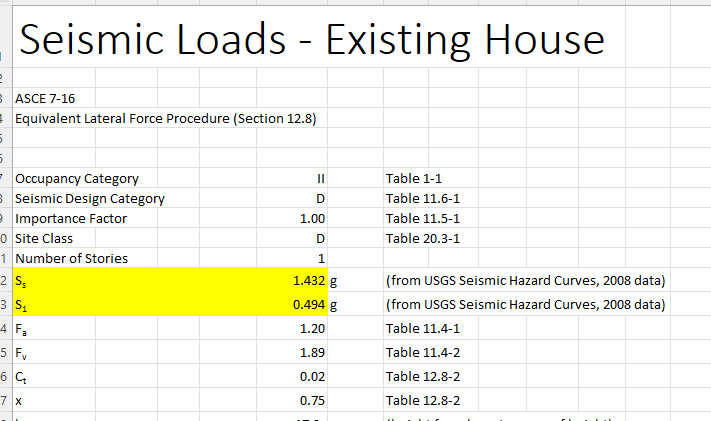
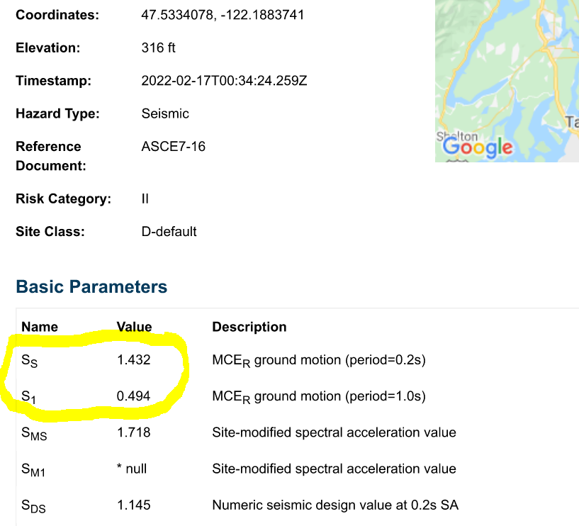
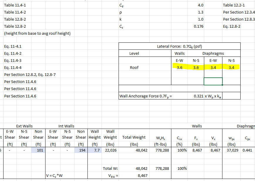
- Fill out Ext. Wall weight and Int. Wall Weight (Calculated on the Assembly Loads tab)
- Fill out Roof Height and Wall Height
- The Height value is equal to the total height between levels- for the Roof Height, this is the average height of the roof. If 2 stories, the Upper floor height is measured from Main Floor T.O. sheathing to Upper Floor T.O. Sheathing.
- Wall Height is equal to plate height (the actual length of the stud member)
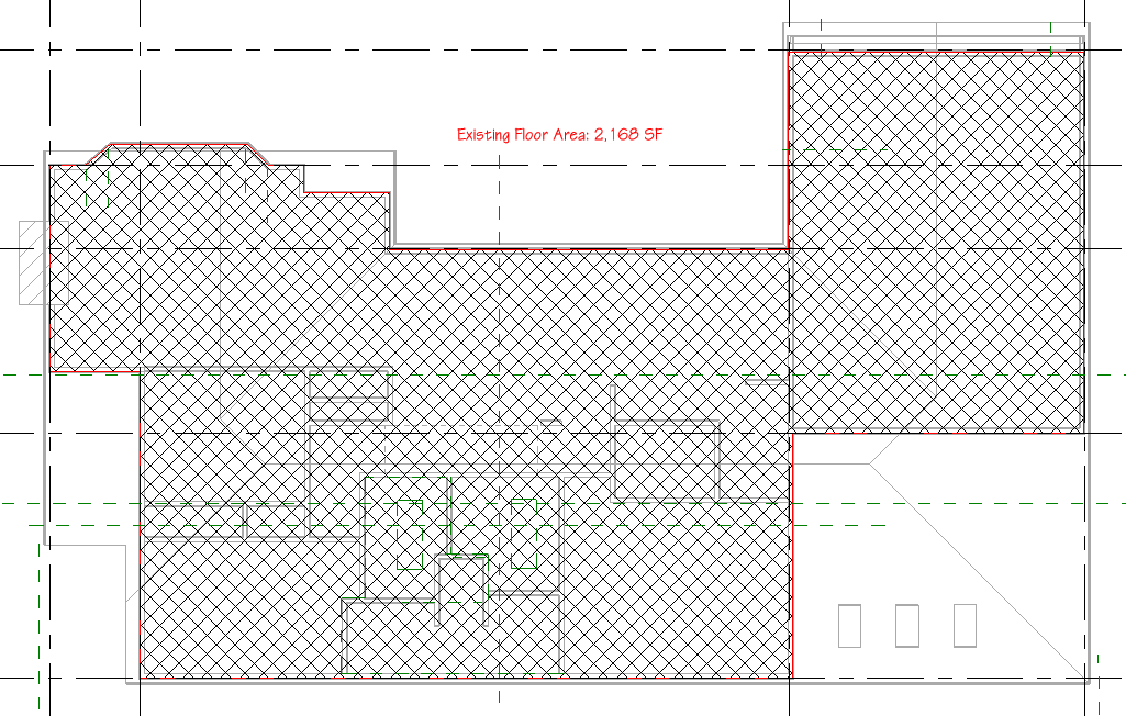
- Fill out Floor Area, and Seismic dead loads (Calculated on the Assembly Loads Tab)
- (To clarify- the upper Floor dead load is just the floor load, do not combine roof and floor load)
- The roof “floor area” is to face of core on the exterior walls, do not include overhangs
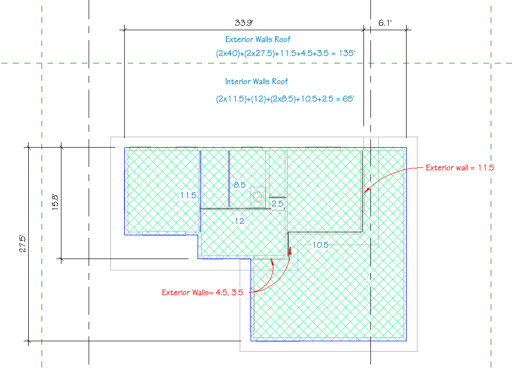
- Calculate the perimeter of the house for length of Ext Walls. Calculate total length of interior walls (round to nearest 1/2 foot for each wall. This can be done by quickly tracing with detail lines the main segments to be counted by breaking it down into vertical and horizontal walls. Look for wall segments that you can combine into one long line segment for measuring efficiency.
- Note- in cases where the walls do not always line up between levels (example: Emerson ADU) pay close attention to which walls count towards which level, and which walls count as exterior versus interior. The EXT walls will include all walls with insulation to account for weight. See example 1 below:
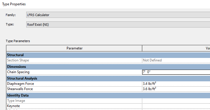
- The Lateral Force table will show the calculated Wall and and Diaphragm forces to plug into the LFRS calculator detail component (in the Type properties)
Wind Loads
- Start with Wind Loads tab for Existing
- Fill out mean roof height, roof pitch, E-W Length and N-S Length of house
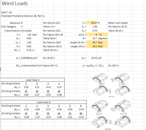
- Check the Windload factors per the jurisdiction (ex. Seattle Wind Load Factors)
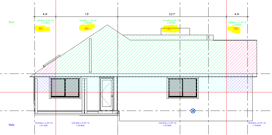
- In the LFRS Elevation views add detail lines to delineate corner effects according to Wind Loads table:
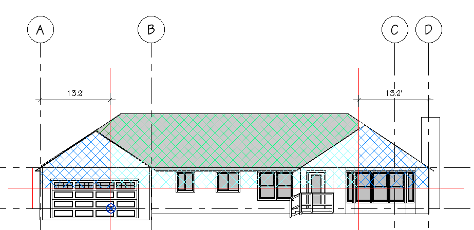
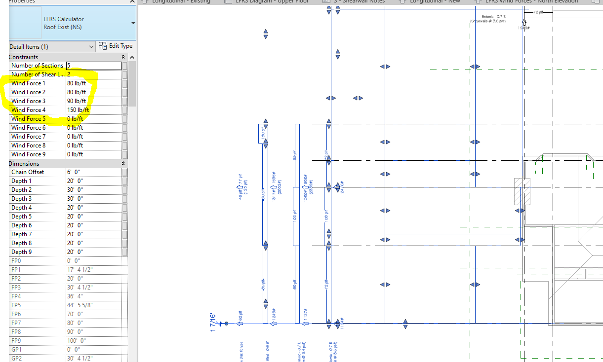
- plug in values into Wind Force Calculator family. It is helpful to use different hatches/ colors to clarify calculated areas.
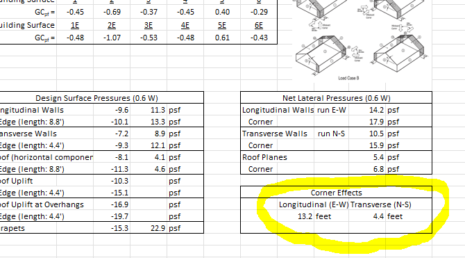
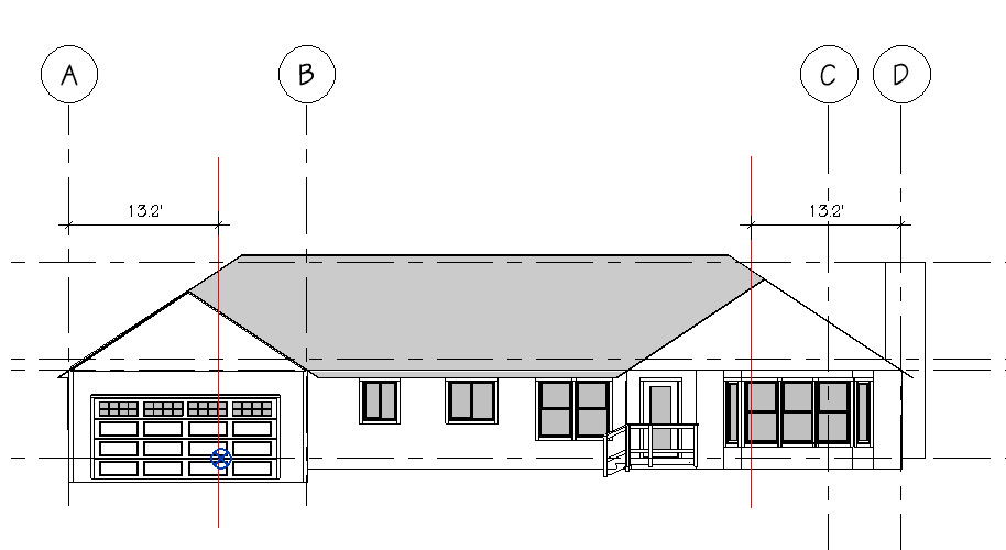
- Create hatches to show area attributed to the roof, walls, and corners accordingly. Divide the middle if needed (typ. where there are large changes in height of roof or walls- sometimes aligned with grid lines or shear walls).
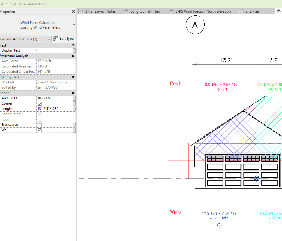
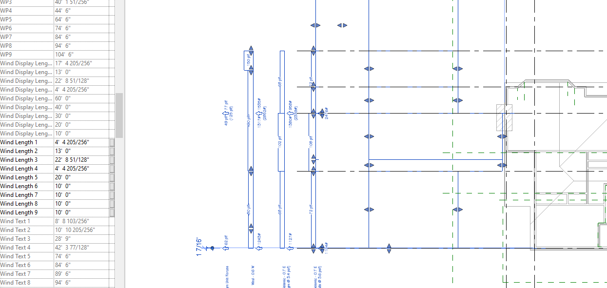
- Add Wind Force Calculators to each section (annotation symbol family) and check correct boxes in the properties. Add length and Area.
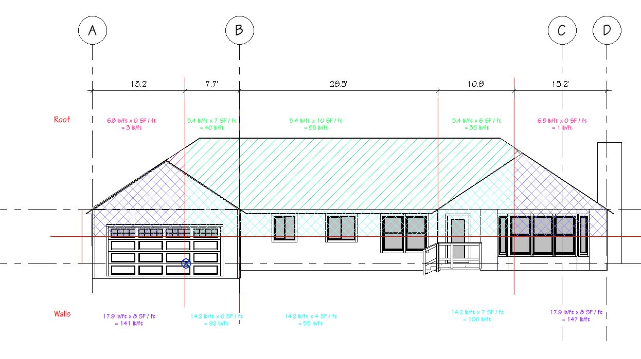
- ex: Longitudinal Wall Corner:
- Add total wind force values (Rounded up to the nearest 10) to the LFRS Calculator
 Repeat with New conditions. Don’t forget to use separate “New Wind Calcs” family and update type properties.
Recent Posts
Categories
- Accessibility (2)
- Annotation Templates (1)
- Building Code (6)
- Calculation Templates (2)
- Civil Engineering (3)
- Derivations (8)
- Drafting Standards (18)
- Energy Code (1)
- Geotechnical Engineering (2)
- IT & Software Setup (5)
- Land Use Code (1)
- Product Knowledge (9)
- Production Tutorial (7)
- Research Notes (9)
- Research Tips (1)
- Revit Families (2)
- Revit Tips (5)
- Standard Operating Procedures (6)
- Stormwater (4)
- Structural Calculators (4)
- Structural Engineering (30)
- Structural General (11)
- Uncategorized (29)