Washington Energy Calcs Basics Tutorial
Last updated October 11, 2024
By Emma Howland
The WSU Code Compliance Calculator offered through the WSU Energy program is a tool for calculating the energy performance for your project. The calculator can be used for both compliance options: the prescriptive path and the Total UA Alternative (or Component Performance) path:
The Prescriptive Path is the most commonly used approach. To demonstrate compliance you must fill out the prescriptive worksheet, glazing schedule, and heating system sizing calculator.
The Total UA Alternative path is a method for performing conductive energy trade offs by trading the R-values and U-factors of the thermal envelope (if the total building thermal envelope UA is less than or equal to the total UA resulting from using the U factors in Table R402.1.3)
This guide is a general overview of the process involved with filling out the Prescriptive Path worksheet
ADDITIONS AND NEW CONSTRUCTION- Prescriptive Path
Setting up
- Open the Group R tab on the bottom of the file to begin.
- Fill out the Project and Contact information
- Choose the correct code compliance pathway- typically Prescriptive path compliance option 1 (preferred)
- Select the Project building type and Occupancy type (R3)

Results
The results section is at the top (a little confusing in my opinion). These calculations update in real time as you fill in the glazing schedule and wall assemblies farther down on the worksheet, so there is nothing you can edit directly in these tables. We will come back to what these calculations mean in relation to energy credits.

Fuel Normalization Credits
The Fuel Normalization credit is an adjustment to account for the carbon emission differences between fuel types for the HVAC system in the house. In this example project, there was an existing gas furnace that will remain, so this project is a Type 1 System (combustion heating equipment) and will receive no credits.

Another common fuel type is a Type 4 system (Electric Resistance with Ductless Heat Pump)- this is often used in ADUs when installing a mini-split system with supplemental cadet heaters. The Normalization credit for this system is 0.5.
Energy Credits
The next table on the form is where the energy credits are selected. This may require some fiddling with, and communicating to the client the options that make sense for the project budget, space, and size before finalizing. Even though it is at the top of the sheet, it may make more sense to select some baseline options, then fill out the rest of the sheet and come back to this section to finalize.
For a general baseline, the “easiest” credits to accommodate in a small addition project (1.5 credits required) is to upgrade the water heater to a Tier 1 heat pump water heater (Option 5.4 = 1.5 credits). Another “easy” pick for a small project is the Appliance Package (7.1) and Efficient HVAC (Options 3 & 4).
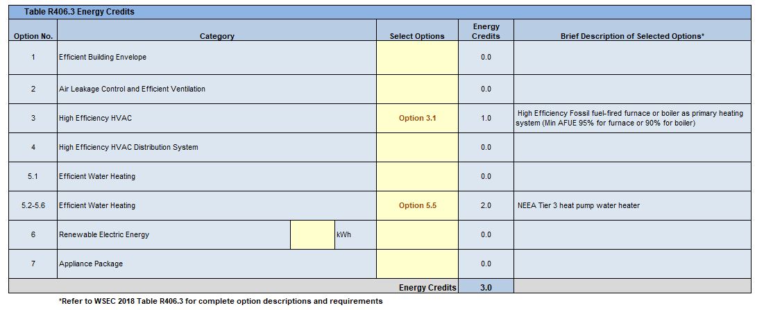
A note- The form is smart enough to know when options are incompatible with the Fuel System when selecting options 3 and 4, so it will have a pop-up warning if something does not coincide with a previously selected option and automatically change the Fuel Normalization Credit System Type. For example, a Type 4 System (Electric Resistance with Ductless Heat Pump) is compatible with Energy Credit Option 3.4 (Ductless Split System, Zonal Control, Min. HSPF of 10, while a Type 1 System (Min. Federal Efficiency combustion system) is compatible with Option 3.1 (High Efficiency Fossil fuel-fired furnace):
Thermal Envelope Details
This is the real start of the form in my opinion. Adding the conditioned floor area at the top of this section will automatically update the “classification” value in the analysis set up at the top of the page and the required credits in the results tab above.
For the conditioned floor area, (measure to the interior face of GWB.)
Exterior Doors & Vertical Glazing Schedule
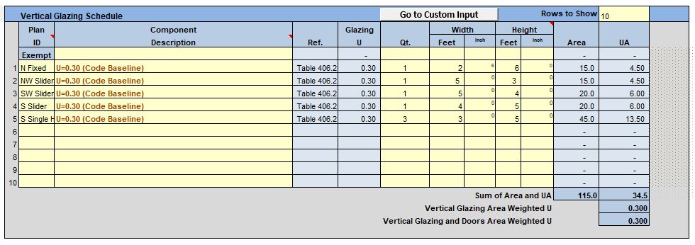
Filling in these schedules is fairly straight forward. The Plan ID system typically depends on how complicated the project is- This example project is a second floor addition, with standard (U-.30) windows:
For larger projects it may be helpful to create a window schedule in Revit first then transfer the window naming system to this worksheet.
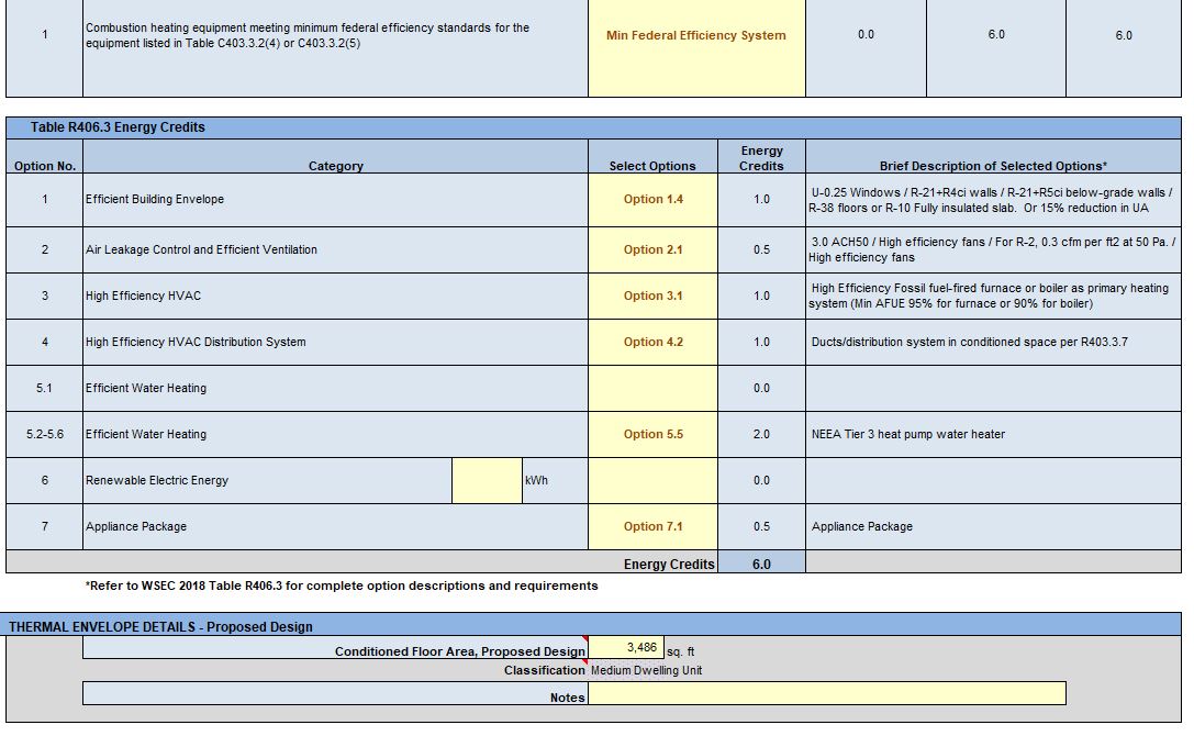
Here is another example of the credits required for a larger addition (Medium dwelling unit = 6.0 credits required). This project required specifying some better U-values for select windows to get to the 15% UA reduction (option 1.4)
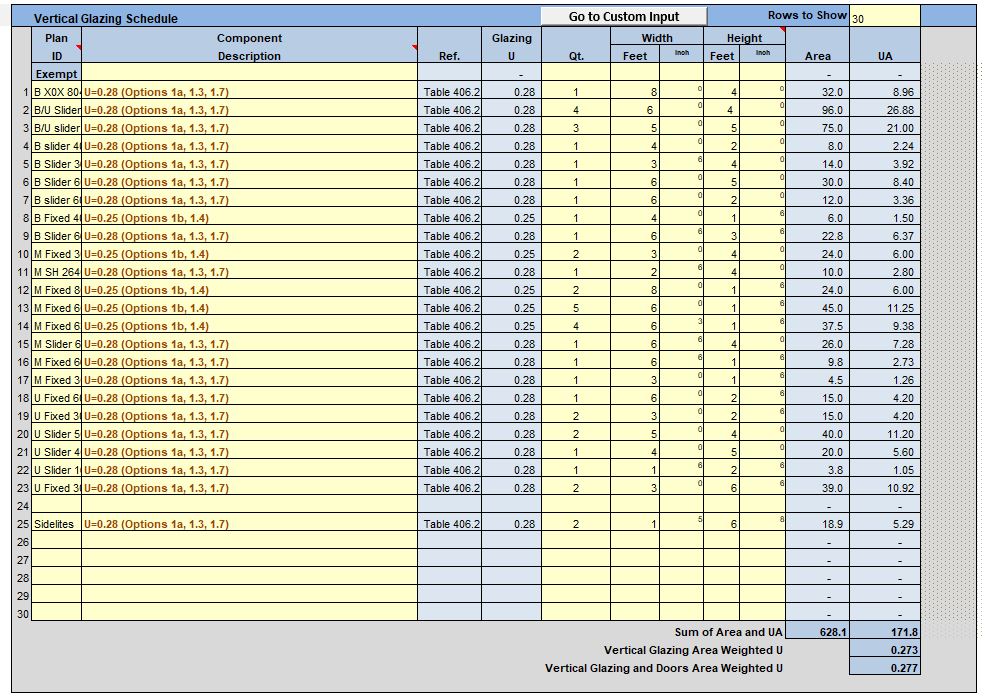
Also note- in the top right corner of the vertical glazing schedule you can adjust the number of rows in the “Rows to Show” input area.

Flat/ Vaulted Ceilings
The next few entries are pretty straight forward, specify the area of the ceilings. (The area of the ceilings should match the conditioned floor area). Then pick the insulation type. If there are multiple areas with different types of insulation break those down into separate entries.

Walls (Above Grade)
For calculating the Wall Net Area, take the perimeter of the exterior walls and multiply by the height of the walls (from T.O. Sheathing to T.O. Plate). Wall heights will likely be different on multi-level projects and projects with shed/gable roofs. Find the average wall height at the midpoint of an irregular wall in this case. And again, If there are multiple wall types with different types of insulation break those down into separate entries.

Floor (Over crawl or exterior)
This category is simple- just take the first floor area (or conditioned floors that are cantilevered on upper stories) and select the component description (most often R30 vented joists at 16″oc.)

Slab on Grade (Less than 2 feet below grade)/ (Below grade Walls and Slabs)
The important distinction on the next two categories is to take the slab perimeter, not the area. The example below is a project with in-floor radiant heating with an insulated slab:
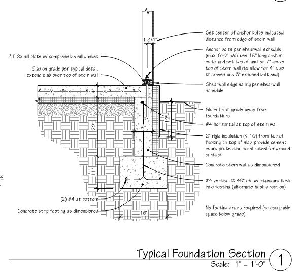

Below is an example of a basement addition:

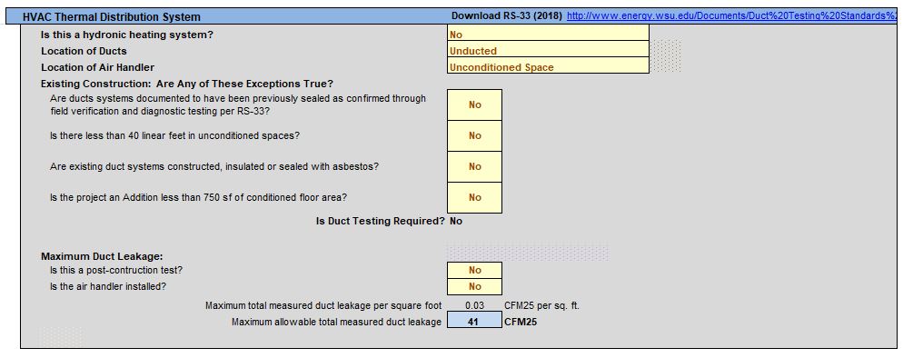
Ventilation Requirements/ HVAC Thermal Distribution System
It is most likely that the project has an unbalanced ventilation system. In the example below, the HVAC system in the second floor addition is a mini-split system so it is Not Distributed (Unducted), and the air handler is located on the exterior behind the garage (Unconditioned Space). Note the Whole house Mechanical Ventilation Airflow Rate (round up to typ. 100 or 150 CFM minimum) as this will be called out in the Cover Sheet notes and on the plans.

Heating System Sizing – Proposed Design
For the majority of projects within the greater Seattle area, it is OK to select the SEATAC airport weather station. The form should automatically calculate the conditioned volume based on all your previous entries with the assumption that there are 8.5′ ceilings. If the ceilings are not 8.5′ you will have to calculate the volume and manually enter it into this field.
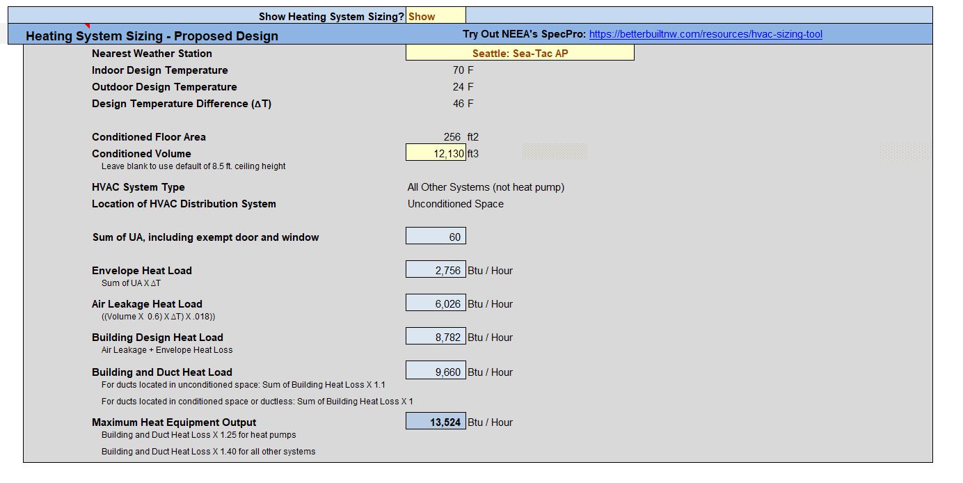
After completing the final section, double check the Results section at the top of the form and make sure the Proposed Design meets the required credits and UA Reduction (if applicable). There may be more tweaking of the insulation types or Window U-values to get the proposed system to meet code, otherwise, save the completed Calcs sheet.
ALTERATIONS
For small remodels that are not adding additional square footage, a separate energy worksheet is required. The example project below required both worksheets because the first floor was being opened up to add a new second story addition.
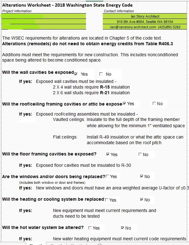
This form is straight forward and short. While filling out this sheet keep in mind how much of the existing structure will be exposed during construction. In this example, almost every part of the structure is affected by the second story addition, even though the windows and HVAC systems will remain.
Recent Posts
Categories
- Accessibility (2)
- Annotation Templates (1)
- Building Code (6)
- Calculation Templates (2)
- Civil Engineering (3)
- Derivations (8)
- Drafting Standards (18)
- Energy Code (1)
- Geotechnical Engineering (2)
- IT & Software Setup (5)
- Land Use Code (1)
- Product Knowledge (9)
- Production Tutorial (7)
- Research Notes (9)
- Research Tips (1)
- Revit Families (2)
- Revit Tips (5)
- Standard Operating Procedures (6)
- Stormwater (4)
- Structural Calculators (4)
- Structural Engineering (30)
- Structural General (11)
- Uncategorized (29)